
A new dimension for drainage design
6 April 2022
3D modelling of structure is now ubiquitous. The ‘realistic’ 3D images are valuable in conveying the design; coordination is made much easier and more democratic in that more parties can input. However drainage still seems to be in 2D CAD, a throwback to how it has typically been designed, by a drainage engineer who draws as they design.
Drainage detail drawings comprise sets of typical standard details. And drainage engineers are often a separate civils team relatively isolated from the main design team. Is this appropriate as we move forward in our increasingly technological, integrated environment? It does not feel right when drainage, especially surface water drainage, has become an increasingly large portion of our work and the construction budget.
A few years ago we abandoned the idea of having a separate civils team. It just wasn’t working for us. It wasn’t ‘Integral’. Instead we invested time and energy to educate all our engineers and technicians in drainage. Now our project engineers know and can control all aspects of our design. An integrated approach with a single clear line of responsibility.
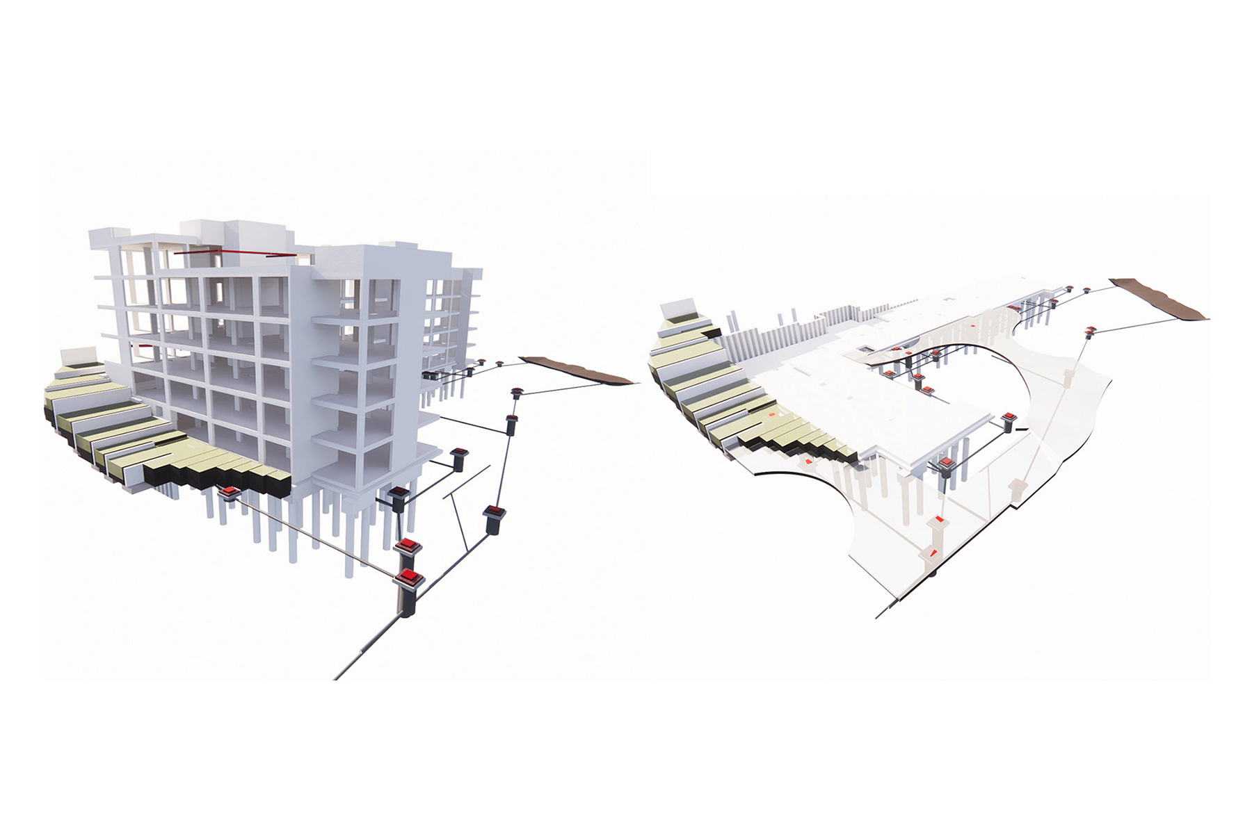
We had had the experience of working on a large project where the contractor asked us to model the drainage in 3D so they could coordinate all the design disciplines in one federated model. At first we literally just built a model from the 2D drawings, effectively running with two sets of information. But this is risky as the information you are going to build from is not the information you are coordinating with.
It therefore made sense to approach drainage design in the same way as structural design where engineers develop a design which is then modelled by our technicians in 3D and the drawings produced from the model. This works for us but we need to produce drawings that look like the traditional 2D line drawings which the industry expects. As an ongoing research project over several live projects and closely supervised, we have written software scripts and created new families within Revit to convert the realistic looking pipes, manholes and tanks in the model into solid and dashed, red and blue lines, symbols and hatched areas.
Our current challenge is to develop ways to model other SuDS features, such as permeable pavements, bioretention features and ponds which we are more and more often part of SuDS driven design that planners and Lead Local Flood Authorities want. Again we are using a real project to ensure we get it right.
It works for us too. Vertical coordination is difficult to do on a 2D plan whereas we can see immediately as we model whether there is a clash. We still produce drawings with typical details but we can supplement these with cut sections at critical interfaces, to show how the tank sits adjacent to the building, how a congested area works or how a series of bioretention features cascade down a slope. This feels more appropriate for the congested or tight brownfield sites we so often deal with now. It also gives contractors confidence and the ability to interrogate the design for themselves through the federated model.
Our next initiative is to collaborate with a landscape architect to maximise the potential of SuDS, the value that gets lost in the grey areas between our disciplines. A bioretention feature is landscape and drainage in one. It needs careful coordination and specification between the disciplines and 3D modelling will facilitate this.
Until recently, 2D drawings were produced out of necessity because 3D technology did not exist. As with structures, it is surely just a matter of time before drainage design shifts wholly into three dimensions. We happen to think that particular future is now.


